Chapter 2:- Periodic Classification of Element
Chapter 3:- Chemical Reaction and Equation
Chapter 4:- Effect of Electric Current
Chapter 5 :- Heat
Chapter 6 Refraction of Light
Chapter 7:- Lenses
Chapter 8 :- Metallurgy
Chapter 9 Carbon Compound
Chapter 10 :- Space Mission
Chapter 4 :- Effect of Electric Current
Textbook Exercise Solution
1. Tell the odd one out. Give proper explanation.
a. Fuse wire, bad conductor, rubber gloves, generator.
Answer:-
Generator
Explanation:- Other Restrict elecric current flow and generator produces Electric current.
b. Voltmeter, Ammeter, galvanometer, thermometer.
Answer:-
Thermameter
Explanation:-
Other measures current while thermometer measures electric current
c. Loud speaker, microphone, electricmotor, magnet.
Answer:-
Magnet
Explanation:- Others used phenomena of electromagnetism while magnet does not.
2. Explain the construction and working of the following. Draw a neat diagram and label it.
a. Electric motor
Answer:-
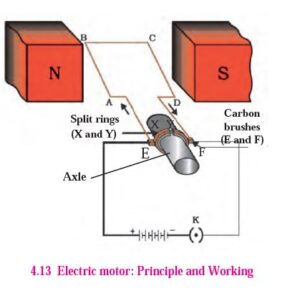
The electric motor is a device that converts electrical energy into mechanical energy. It consists of several parts, including:
Rectangular loop of copper wire: This is the main component of the motor, and is wound in the shape of a rectangular loop with a resistive coating.
North and south pole magnets: These provide the magnetic field required for the motor to function. The rectangular loop is placed between the north and south pole magnets in such a way that its branches AB and CD are perpendicular to the direction of the magnetic field.
Split ring: The two ends of the rectangular loop are connected to the two halves (X and Y) of the split ring. The two halves of the ring have a resistive coating on their inner surfaces and are tightly fitted on the axle.
Carbon brushes: The two halves of the split ring, X and Y, have their outer conducting surfaces in contact with two stationary carbon brushes, E and F, respectively. These brushes allow current to flow from the battery or power source to the loop.
Working: When the circuit is completed, current flows in the branch AB of the loop from A to B through the carbon brushes E and F. According to Fleming’s left-hand rule, a force is exerted on the branch AB and pushes it down. The current in the CD branch is in the opposite direction to that in the AB branch, and therefore, a force is exerted on the branch CD in an upward direction. This causes the loop and the axle to start rotating in an anticlockwise direction. After half a rotation, the split ring X and Y come in contact with carbon brushes F and E, respectively, and the current in the loop starts flowing in the direction DCBA. Therefore, a force is exerted on the branch DC in a downward direction and on the branch BA in an upward direction, and the loop continues to rotate in the anticlockwise direction. Thus, the current in the loop is reversed after each half rotation, and the loop and the axle continue to rotate in the anticlockwise direction.
b. Electric Generator(AC)
Answer:_
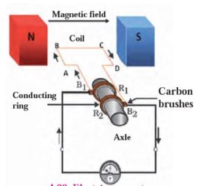
An electric generator is a device that converts mechanical energy into electrical energy. The generator consists of a coil of wire, usually copper, which is placed between the two pole pieces of a magnet. The coil is rotated around an axle with the help of a machine. The coil rotates in the magnetic field and produces an electric current. The different parts of an electric generator are:
Coil: The coil is made of copper wire and is usually in the form of a rectangular or circular loop.
Magnet: The magnet creates a magnetic field in which the coil rotates. The two pole pieces of the magnet are placed on either side of the coil.
Conducting rings: The conducting rings are fixed to the axle and are connected to the two ends of the coil via carbon brushes. These rings are used to collect the current generated by the coil.
Carbon brushes: The carbon brushes are stationary and are in contact with the conducting rings. They are used to transfer the current from the conducting rings to the external circuit.
The working of an electric generator is based on Faraday’s law of electromagnetic induction. When the coil rotates in the magnetic field, a voltage is induced in the coil. This voltage is directly proportional to the rate of change of magnetic flux through the coil. The induced voltage causes an electric current to flow through the coil, and this current is collected by the conducting rings.
As the coil rotates, the direction of the current in the coil changes. This is because, after every half rotation, the brush contacts switch and the current flows in the opposite direction. This produces an alternating current (AC) in the external circuit.
The construction of commercial generators is similar to the basic design, but practical changes are made to improve their efficiency and performance.
3. Electromagnetic induction means
a. Charging of an electric conductor.
b. Production of magnetic field due to a current flowing through a coil.
c. Generation of a current in a coil due to relative motion between the coil
and the magnet.
d. Motion of the coil around the axle in an electric motor.
Answer:-
Generation of a current in a coil due to relative motion between the coil
4. Explain the difference :
AC generator and DC generator.
| AC generator | DC generator | |
| i. | It is used to produce alternating current. | It is used to produce direct current. |
| ii. | It has two simple ring-type commutators. | It has a single split-ring commutator. |
| iii. | Frequency of induced current is 50Hz. | Frequency of induced current is 0Hz. |
| iv. | Current changes its directions. | Current flows in same direction. |
5. Which device is used to produce electricity? Describe with a neat diagram.
a. Electric motor
b. Galvanometer
c. Electric Generator (DC)
d. Voltmeter
Answer:_
Answer:_
An electric generator is a device that converts mechanical energy into electrical energy. The generator consists of a coil of wire, usually copper, which is placed between the two pole pieces of a magnet. The coil is rotated around an axle with the help of a machine. The coil rotates in the magnetic field and produces an electric current. The different parts of an electric generator are:
Coil: The coil is made of copper wire and is usually in the form of a rectangular or circular loop.
Magnet: The magnet creates a magnetic field in which the coil rotates. The two pole pieces of the magnet are placed on either side of the coil.
Conducting rings: The conducting rings are fixed to the axle and are connected to the two ends of the coil via carbon brushes. These rings are used to collect the current generated by the coil.
Carbon brushes: The carbon brushes are stationary and are in contact with the conducting rings. They are used to transfer the current from the conducting rings to the external circuit.
The working of an electric generator is based on Faraday’s law of electromagnetic induction. When the coil rotates in the magnetic field, a voltage is induced in the coil. This voltage is directly proportional to the rate of change of magnetic flux through the coil. The induced voltage causes an electric current to flow through the coil, and this current is collected by the conducting rings.
As the coil rotates, the direction of the current in the coil changes. This is because, after every half rotation, the brush contacts switch and the current flows in the opposite direction. This produces an alternating current (AC) in the external circuit.
The construction of commercial generators is similar to the basic design, but practical changes are made to improve their efficiency and performance.
6. How does the short circuit form?
What is its effect?
Answer:_
A short circuit forms when the ‘live’ and ‘neutral’ wires of an electrical connection come in contact with each other due to a fault in the equipment or when the plastic coating on the wires gives way. This creates a path of low resistance and a large current flows through it, producing heat. If there are any inflammable materials in the vicinity, they can catch fire.
The effect of a short circuit can be dangerous and can cause fires or electrical shocks. To avoid such mishaps, a fuse wire is used as a precautionary measure. As soon as high current flows in a circuit, the fuse wire melts and breaks the circuit, preventing any further damage. Overloading of the transformer supplying electricity can also cause the fuse wire to melt and shut down the supply.
7. Give Scientific reasons.
a. Tungsten metal is used to make a solenoid type coil in an electric bulb.
Answer:-
Tungsten metal is used to make the filament in an electric bulb, which is a type of solenoid coil. This is because tungsten has a very high melting point (3422 °C), which allows it to withstand the high temperatures generated by the electric current passing through it without melting. The filament in an electric bulb is designed to glow brightly when electricity passes through it, and tungsten’s high melting point allows it to maintain its shape and structure while glowing brightly for a long period of time. Additionally, tungsten has a low coefficient of thermal expansion, which means that it does not expand or contract significantly when it is heated or cooled, making it an ideal material for use in the filament of an electric bulb.
b. In the electric equipment producing heat e.g. iron, electric heater, boiler, toaster etc. an alloy such as Nichrome is used, not pure metals.
Answer:-
In electric equipment that produces heat, alloys such as Nichrome are commonly used instead of pure metals. Nichrome is an alloy made from nickel, chromium, and iron, and it has a high electrical resistance, which allows it to convert electrical energy into heat. It also has good oxidation resistance and mechanical properties, making it a suitable material for use in heating elements in appliances such as irons, electric heaters, boilers, toasters, and other similar equipment. The use of Nichrome and other alloys allows for efficient and reliable heat production in these devices.
c. For electric power transmission, copper or aluminium wire is used.
Answer:-
Copper and aluminum wires are commonly used for electric power transmission, depending on the specific requirements and characteristics of the transmission system.
Copper has higher electrical conductivity than aluminum, which means that it can transmit electricity more efficiently. However, copper is also more expensive than aluminum, so it may not always be the most cost-effective option. In some cases, the lower cost of aluminum may outweigh its lower electrical conductivity, making it a more practical choice.
Overall, both copper and aluminum have their advantages and disadvantages, and the choice of which one to use for electric power transmission depends on various factors such as the distance of transmission, the amount of power being transmitted, and the cost-effectiveness of the materials.
d. In practice the unit kWh is used for the measurement of electrical energy, rather than joule.
Answer:-
In practice, the unit kWh (kilowatt-hour) is commonly used for the measurement of electrical energy consumed or produced over a period of time, rather than joule.
The kilowatt-hour is defined as the amount of energy consumed or produced by a device with a power rating of 1 kilowatt (1000 watts) over a period of one hour. This unit is used extensively in the electric power industry to measure the amount of energy consumed by households, businesses, and industries. It is also used to measure the output of power plants and renewable energy sources.
The joule is the standard unit of energy in the International System of Units (SI), but it is not commonly used to measure electrical energy in everyday situations because the quantities involved are often very large. One kilowatt-hour is equivalent to 3.6 million joules, so the use of the kWh unit provides a more convenient and practical way of measuring electrical energy in everyday situations.
8. Which of the statement given below correctly describes the magnetic field near a long, straight current carrying conductor?
a. The magnetic lines of force are in a plane, perpendicular to the conductor in the form of straight lines.
b. The magnetic lines of force are parallel to the conductor on all the sides of conductor.
c. The magnetic lines of force are perpendicular to the conductor going
radially outward.
d. The magnetic lines of force are in concentric circles with the wire as the center, in a plane perpendicular to the conductor.
Answer:-
d. The magnetic lines of force are in concentric circles with the wire as the center, in a plane perpendicular to the conductor.
9. What is a solenoid? Compare the magnetic field produced by a solenoid with the magnetic field of a bar magnet. Draw neat figures and name various components.
Answer:-
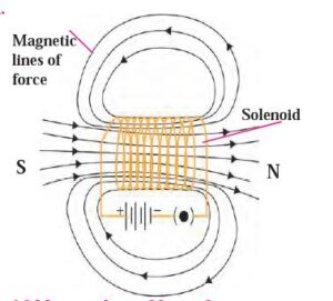
When a copper wire with a resistive coating is wound in a chain of loops (like a spring), it is called solenoid. Whenever an electric current passes through a solenoid, magnetic lines of force are
produced in a pattern as shown in figure 4.9. You are aware of the magnetic lines of force of a bar magnet. The properties of the
magnetic field of a solenoid are very similar to the magnetic field produced by a bar magnet. One of the open ends of a solenoid acts as a magnetic north pole and the other as the magnetic south pole. The magnetic lines of force inside the solenoid are parallel to each
other.
10. Name the following diagrams and explain the concept behind them.
Answer:-
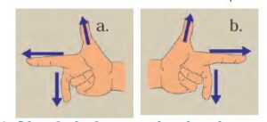
First figure is of Flemings right hand Thumb rule
This is a convenient rule for finding out the direction of the magnetic field produced by a current flowing through an electrical conductor. Imagine that you have held the conductor in your right hand in such a way that your thumb points in the direction of the current. Then turn your fingers around the conductor, the direction of the fingers is the direction of the magnetic lines of force
Second Figure is of Flemings left hand thumb rule
According to this rule, the left hand thumb, index finger, and the middle finger are stretched so as to be perpendicular to each
other. If the index finger is in the direction of the magnetic field, and the middle finger points in the direction of the current, then the direction of the thumb is the direction of the force on the conductor.
11. Identify the figures and explain their use.
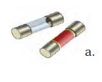
Above figure is of Cartridge type fuse
Use:-
Cartridge type fuses are commonly used to protect electrical circuits from overcurrent conditions. They consist of a cylindrical body made of ceramic, glass, or other insulating material, with metal end caps that provide electrical connections to the circuit.
Cartridge fuses are designed to be inserted into a fuse holder or fuse block that is mounted on a panel or circuit board. When the current passing through the circuit exceeds the rated value of the fuse, the fuse wire inside the cartridge melts, interrupting the flow of current and protecting the circuit from damage.
One advantage of cartridge fuses is that they are available in a wide range of current ratings and sizes, making them suitable for use in a variety of applications, from low-power electronic circuits to high-power industrial machinery. They are also easy to replace, as the entire cartridge can be removed and replaced with a new one.
Cartridge fuses are commonly used in applications such as power distribution, motor control, and lighting systems, where protection against overcurrent conditions is necessary to ensure safe and reliable operation of the equipment.
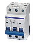
Above figure is of MCB
MCB stands for Miniature Circuit Breaker, which is an electrical protection device designed to protect electrical circuits from overcurrent conditions. MCBs are commonly used in residential, commercial, and industrial applications, and are typically installed in electrical panels or distribution boards.
The main function of an MCB is to automatically interrupt the flow of current when it exceeds a certain threshold, typically due to a fault or overload condition in the circuit. This protects the electrical equipment and wiring from damage, and also helps to prevent fires and other hazards.
MCBs are designed to be more precise and responsive than traditional fuses, which can be slower to react to overcurrent conditions. MCBs typically have a quick trip mechanism that allows them to detect and respond to overcurrent conditions in milliseconds, which helps to prevent damage to the circuit and connected equipment.
In addition to their high level of protection, MCBs are also easy to reset after an overcurrent condition, and do not require replacement like traditional fuses. This makes them a more convenient and cost-effective option for protecting electrical circuits in a variety of applications.
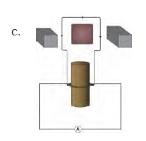
Above figure is of DC generator
It is a device that generates electricity by rotating its rotor in a magnetic field. Thus, it converts mechanical energy into electrical energy
12. Solve the following example.
a. Heat energy is being produced in a resistance in a circuit at the rate of 100 W. The current of 3 A is flowing in the circuit. What must be the value of the resistance?(Ans : 11 W)
Answer:-
Given:
Power, P =100 W
Current, I = 3 A
Resistance, R = ?
We know, P = I2R
b. Two tungsten bulbs of wattage 100 W and 60 W power work on 220 V potential difference. If they are connected in parallel, how much current will flow in the main conductor?
Answer:-
Potential remains same in the resistors when they are connected in the parallel.
∴ Potential in both the bulbs will be same.
Now,
For First Tungsten Bulb,
Power = 100 W.
Potential = 220 V.
∵ Power = Potential × Current.
∴ Current = 100/220
⇒ Current = 0.45 A.
For second Tungsten bulbs,
Power = 60 W.
Potential = 220 V.
∴ Current = 60/220
= 0.27 A.
Now, Total current flowing = Current in 1st bulb + Current in 2nd bulb.
= 0.45 + 0.27
= 0.72 A.
Hence, the total current flowing in the main conductor is 0.72 A.
c. Who will spend more electrical energy? 500 W TV Set in 30 mins, or 600 W heater in 20 mins?
Answer:_
For T.V. set: Power = 500 W,
Time = 30 min = 30 × 60 s
∴ Energy = Power × time
E1 = 500 × 30 × 60 = 900 × 103 J
For Heater: Power = 600 W,
Time = 20 min = 20 × 60 s
∴ Energy (E2) = 600 × 20 × 60
= 720 × 103 J
Comparing E1 and E2, E1 > E2
∴ Energy spent by T.V. set (E1) is greater.
The energy consumed by T.V. set is more than that consumed by heater.
d. An electric iron of 1100 W is operated for 2 hrs daily. What will be the electrical consumption expenses for that in the month of April? (The electric company charges Rs 5 per unit of energy).
Answer:-
Electric power required for working of iron, P = 1100 W
Duration for which the iron is operated daily = 2 h = \[2 \times 60 \times 60 = 7200 s \]
Electric energy consumed by iron in 7200 s is
or, \[1 J = \frac{1}{3 . 6 \times {10}^6} \] unit
Thus,
\[237600000 J = \frac{237600000}{3 . 6 \times 1000000} = 66\] units